Laser cutter aligning
January 2020 Andy and Jon did some much needed maintenance on the laser cutter, cleaning the bed and doing some aligning.

It was clear, however that we didn't know all we needed, so we asked for some help and Steve and Ru from Reading came to help. They even came bearing a gift, made on their laser cutter, through clever manipulation of mapping software written by Vance and tweaked by Tony

Over a year and one pandemic later, Andy's finally writing up the notes as it's likely he'll have to do the same thing again as we move it into it's new home in the office.
Time Taken
To read this?
Grab a coffee, all mistakes are my own but, honestly, it's more a big brain dump/ note to self than for other people but apologies all the same.
Aligning process:
- Gets quicker with practice but a full adjustment (and clean of machine) with a new tube is a day.
- Minor adjustments is probably a few hours, depends how bad it is
What causes misalignment?
- Regular Use - vibration, heating cooling, knocking of machine/ head into work etc
- Maintenance - Replacing mirrors, lenses etc
- Moving machine - we need to think about the placement of our machine and what access we can get to it without having to wheel it out every time.
Our Laser
Model: KH-7050-B (KH750) Also knows as Redsail X700 clone
Useful website from Lansing Makers in the states
Control Board: Software says it's a 644XG, need to confirm
Chiiler unit: Applied Thermal Control ktc 2460
Lens: Lenses are available in bi-convex, plano-convex and meniscus. Meniscus tend to work best in this type of cutter. Always install with the convex surface upwards. Me, confirm lenses as made a mistake before, they're either 20 or 25mm
Mirrors: Available in Molybdenum, Gold, Silicon or Copper. Molybdenum are most durable and worth the cost, Gold have the highest performance but are delicate and expensive, copper and silicon are cheap but delicate and need frequent cleaning.
Software: We use RDworks but you may choose to investigate Lightburn
From this process I recut our spacer to Me, confirm but I think 19mm and it was cutting significantly better
Tools
DoHickyTM
Although this isn't critical to this process it's worth a mention...
Russ from SarbarMultimedia (formerly RDworks learning labs) kindly gave us this, with a nice note "Please accept this little lump of metal as appreciation for what you are doing for your local community."
I highly recommend his videos if you're interested in mastering the all aspects of using the laser. It's essentially a thermocouple with an anodised aluminium body A zip of relevant files is uploaded File:Dohicky.zip there's more from other videos Rdworks forums Sign up required
It also came with a warning
"What ever you do never measure the power at the focus point of your lens because the energy density is high enough to etch off the anodized surface Make sure you test it 2 or 3 inches below your nozzle. At all other points the beam is about 6mm diameter and has very low energy density."
Targets
Jon made this as while ago include file when Jon sends it although we found masking tape quick and easy on the day and the targets had a habit of leaving ash on the mirror, a double layer of masking tape may work better sometimes, try it and see. Test shots should be done at substantially reduced power as the beam from the tube is better behaved at lower powers and so easier to align. Minimum power is How much?

Safety
We'll be working with the lid up for a lot of this so:
- Warning signs on doors, no-one not involved with the procedure should be present and anyone else who might be nearby needs to be warned
- Eye protection on at all times, the more face-hugging and all-covering the better
- Mind the laser beam, it's easy to be focusing on the mirrors and put a hand tool in the path
- Equally mind where the laser is going from where you're focusing it, don't send it into a cable accidentally.
- So when focusing the next mirror, start by moving the rail close by
- Relatively small adjustments of the housing can massively impact the beam and there's wires, belts and fingers to hit
- The lenses are made of Zinc Selenide which is toxic, but it's only hazardous through ingestion or dust inhalation so it's normally not a problem. If you do crack or chip a lens then be careful. In any event always wash hands before and after handling lenses. Some guides recommend the use of acidic cleaners like vinegar, but this is not a good idea because if there are any scratches in the optical coating and the acid is able to reach the zinc selenide it will produce a hazardous gas (Hydrogen Selenide)
READ THIS - YOU HAVE BEEN WARNED
* Goggles will block scattered beam and diffuse reflections, but will NOT save you from a direct hit from the beam. Without goggles even a glancing hit from an unfocused beam will blind you before you can blink, with goggles you're safe from brief glancing strikes from the beam, and from scatter and diffuse reflection but a direct hit from the focused beam will burn through the goggles in a fraction of second.
* Better goggles that can stop a direct hit from the beam exist, but they cost hundreds to thousands of pounds, the market is flooded with fakes, and there's no non-destructive way to test them.
* Also note that there are sometimes "parasitic" beams that emerge from the laser tube at weird angles so keep the lid close except when working on mirror.
* You may have also noticed me shielding my eyes from direct-line-of-sight to the tube with my hand sometimes when I was at a shallow angle to the tube and the covers were open. A strike to the hand would hurt like hell, but such things heal, eyes don't.
Aligning Process
Introduction

Some key ideas to start
- We're numbering the mirrors here in the order from the beam to the head. Mirror 1 is stationary and located immediately next to the end of the laser tube, mirror 2 is located on the end of the main moving beam, mirror 3 is located directly above the cutting head
- You adjust in the order of the path e.g. Mirror 1 in front of the tube then following the path along to the cutting end
- We're trying to ensure the path is straight through all the mirrors and hitting the lens at the centre.
- Getting the beam hitting the same spot as a mirror travels along it's rail is vital
- Getting the beam hitting dead centre also important, although not as critical as getting it hitting the same spot all the time - the beam should to hit the final lens dead centre, or it will be angled off and cuts will be slanted or tapered
- This is a VERY iterative process, once you've adjusted one mirror, you need to retrace your steps from mirror one to confirm you're still hitting all of them. Dozens to hundreds of adjustment cycles will be needed
- Housings: The black assemblies bolted into the frame that the mirrors sit in
Pre-checks
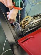
- Confirmed the reading on the ammeter with the fluke, the current when the controller is calling for 100% should be at or below the rated current of the tube. Only do current checks on the return side of the PSU, checking the hot leg or breaking the return leg circuit can make the meter come up to +30Kv with enough current to kill! Set the meter up for current display then DON'T TOUCH IT during the test. Over-current conditions drastically shorten tube life, under-running the tube can greatly extend life. Even under the best circumstances it's unlikely the tube will still produce a good beam beyond 2000 hours of use (from internal degradation) or 5 years from manufacture date (from Helium leakage), whichever comes first.

- Test the condition of the laser tube by firing the unfocused beam from the tube directly into a thick acrylic block, positioning it so that the beam goes directly from the tube to the block without bouncing off of any of the mirrors. Block should be a minimum of 10mm thick and thicker is better, you'll need to keep the block completely still and direct a jet of compressed air onto it to prevent smoke and flames which will require a firm mounting. Fire the beam at maximum power for 5-10 seconds. This etches an image of the beam's power profile into the acrylic so you can check how it's doing. You're hoping for a clean Gaussian beam profile that's just a little bit pointed in the centre. If the pattern is asymmetric, has more than one peak, or has rings on it then that indicates that the tube is no longer operating in TEM00 mode. There's nothing much you can do about this other than replacing the tube but it's worth knowing cause if the tube is wearing out then you won't be able to get a tight focus no matter what you do and it can save frustration to know this.

- Use the DohickyTM to take readings if you want a comparison at the end
Mirror Alignment
All mirrors allow similar alignment within their housing through 3 nuts.
- Need 8mm spanner to undo locking nuts - remember to do them up after
- Some a small application of nail varnish may help keep them in place at the end of the process.
- Remove with acetone
- Some a small application of nail varnish may help keep them in place at the end of the process.
In addition the housings allows alignment in:
- Mirror 1: Z axis, rotational
- Mirror 2: Y axis; and XY-combined (45 degrees) using nuts underneath
- Mirror 3: allows some adjustment in XZ combined by moving all adjuster screws at once but only by very small amounts.
Errors
This is the key thing Jon and I were trying to do at once that made it harder. Processes are good...
There are two types of errors we want to correct here.
Angular
Adjusting the mirror in the bracket to target the mirror and get the spots in the same place on the next mirror, regardless of where that mirror is on it's rail i.e. close or far
- Beam is not straight:
- It's not hitting the same spot on the next mirror when the next mirror is near and far
Translational
Adjusting the bracket that the mirror sits in to move the, now straight, laser in xyz
- Beam is straight up to the next mirror but too high/ far to one side
- Move the housing to correct this
You do them in that order, but correct the angular again after the translational adjustments. That mirror should be hitting the next one dead centre whatever it's position by the time you've finished.
Process
- Iterative process of adjusting each mirror in order.
- First to remove the angular error
- Then to remove the translation error
- Go back to the mirror you were adjusting to correct the angular error as you've now moved the whole housing
Be careful about the beam shooting off here as you've made adjustments
- Once you've adjusted one mirror you will need to go back and confirm the previous mirror is still hitting the mirror you've adjusted in the centre.
- Repeat all the way down back the chain if you've adjusted the previous mirror
- Go back to the mirror you were adjusting and repeat the process
Example
As an example - aligning mirror 2
- Mirror2 is hitting mirror 3 off centre and also in different points depending where mirror 3 is on it's travel
- Mirror one is hitting mirror 2 dead centre at all points of it's travel as we've done this process on mirror 1 already
Steps
- First ensure you've got enough travel on the screws to adjust mirror2 (rather than housing). If not centre it and move the housing until you're on target enough to start the process.
- Put white tape on mirror 3 and adjust correct the angular error - so that it's hitting mirror 3 at the same point on the tape
- Adjust the housing to move the beam as needed centre the beam for height/ XY-combined axis
- Now we need to go back and confirm that mirror 1 is hitting mirror 2 in the centre at all points of it's travel. Likley not as we've moved it.
- If that ends up with moving the housing of mirror 3, we need to confirm it's being hit in the centre by the tube (although this is a bit easier as mirror 1 doesn't travel along a rail)
- Then repeat the adjustment of mirror2.
Remember the need to clean a mirror every time you take the tape off. Acetone works, but optical Methanol is better. Using cotton buds with the smooth rolling action to avoid grinding dirt into the mirror.
Beam Vertical checks
Similar to previous adjustments - we detach the head and put some tape over the now-open tube to align mirror 3
- But the true check is whether the beam is vertical after the lens
- We need to confirm it's coming out of the lens straight (pick one/ both methods)
- Check beam is hitting same spot at different heights:
- Fire sustained beam into thick acrylic to check the beam is straight and parallel
- Repeat across bed, accepting that the bed is wonky but that's another day's challenge
- Beam also needs to hit the lens centrally, moving all 3 adjusters in/out together will move mirror-3 in the X-axis to correct that, if it's out in the Y-axis you need to translate the position of mirror-2. We didn't have to do anything to mirror-3 cause whoever adjusted it last got it right.
- It's only at this point you'll know for sure if the tube height is correct. If it's wrong it you'll find it impossible to get the beam striking the lens and/or mirror 3 to be both angularly and translationally correct.
- If this happens then the entire laser tube has to be moved up or down. After that, you're back to square-one on the mirror alignments.
- We didn't have to do this because your tube height was correct.
End Checks
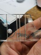
Fire the beam into acrylic from different heights around the focussing height to check it's still the same (better)- you can see here it
Power
We were over driving the tube Looking at https://www.cloudraylaser.com/products/35-45w-720mm-co2-laser-upgraded-metal-head-tube-cr35?variant=12782294270003 A 60W tube shouldn't run above 20mA
Some laser power supplies have a way to adjust that, a screw on the supply. We opened ours and it didn't.
This confirms that we shouldn't power the tube more that 70% which matches with our previous tests I've now changed the firmware to limit the power there... you can still enter 90 in the software but the board will still output 70
Tests
- Four-corners shot test to check for complex geometry errors
- (once you have lightburn) automated focal height check, it often shifts
End product
A beam about 0.2-0.3mm at the focal point. Diffraction limited spot size depends on lens focal length and beam diameter but is typically around 0.2mm for machines of this class, focusing tighter than this will never be possible, and the limit will be worse if the tube is old/degraded/poor quality
Tips for cutting
- For materials that burn, focus the beam 1/3 from the top of the material
- For materials that melt, focus the beam 1/3 from the bottom of the material
Maintenance Tasks
It's a handy time to also carry out
- Cleaning everything you see, mirrors especially as the whole power of the machine relies on these
- Kim does a good job of this but you've got more access
- Cleaning of the lens using cotton buds/lint free cloth and optical (99.9% pure, water-free) methanol. Avoid water or anything acidic (toxic gas risk)
- Mirrors come in several types, Molybdenum mirrors are extremely hard and durable and can be cleaned quite aggressively. Gold, Silicon or Copper mirrors are much more delicate and so each cotton bud or cloth should be used only once and wiped across the mirror in one direction only, this avoids picking up grit and grinding it into the mirror.
- Lenses are more delicate, on a par with silicon mirrors, and should be cleaned with a similar procedure.
- Cleaning early and often prevents soot/smoke/tar residues from building up then getting baked onto the optics making cleaning much harder
- Clean Filters - air pump and electronics bay
- We should do this once a month - we don't
- Check/ Clean air paths - use the compressor
- We should do this once a month - we don't
- Clean and re-oil the rails with a light machine oil like 3-in-1.
- Oil once heavily, leave an hour or so to dissolve old oil
- With a soft cloth wipe off all the now dirty oil
- Apply fresh oil, only a very thin coating is needed, it should never drip. Can be applied using a soft cloth to wipe the oil on
- Checking tube power for over-driving (more amps than the tube can take drastically reduces it's life), relationship is worse than inverse-4th-power
Photos
For the really keen some photos and what they mean
-
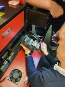
Examining the board
-
Beam Profile
-
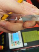
Beam Mode
-
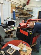
Thanks again
-
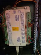
Main Board
-
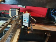
Not dead centre
-
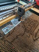
Beam Vertical checks
-
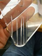
Wonky Beams
-
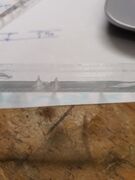
Depth of cut
-
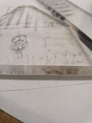
Pin holes
-
Laser modes


| Image Caption | Explanation |
|---|---|
| Examining the board | Steve and Ru will claim they were doing something important here but I suspect they just like looking at electronics boards, who doesn't? |
| Beam Profile | See the prechecks section, we're checking the beam here |
| Beam Mode | Here we see that the beam has a TEM10 mode (Transverse Electromagnetic Modes), more a charactestic of the tube than anything we alter
This is not something you need to understand for this process but there's some more on modes here http://www.aml.engineering.columbia.edu/ntm/level2/ch02/html/l2c02s07.html |
| Thanks again |
As you can see from Steve's face, this is way past the point where they both realised how little help I would be during this process. Jokes on me, I'm on my own next time |
| Main Board | Who doesn't love a board pic |
| Not dead centre | A good way of marking the location |
| Beam Vertical checks | See the Beam Vertical checks section to understand these |
| Wonky Beams | PEW PEW, LASERS -Can you tell I've been at this a while?
Are we testing depth of cut here, or the straightness of the beam? Why are we doing it on a corner piece? Mavericks! |
| Depth of cut | We're just showing here that we're getting a decent amount more penetration here than before we started. |
| Pin holes | This is where we're pulsing the beam into the material to check that the beam profile and direction are consistent at all 4 corners of the bed. A good result is all 4 holes the same size, pointing in the same direction, and with an even and symmetric melt-zone around them |
| Laser modes | If you get engineers together, someone's going to draw a diagram
Laser mode changes with power, the more power you put into the tube the faster it will cut, up to a point.... As power increases the chance of undesirable parasitic modes occurring increases and the beam quality degrades, this is a function of the tube quality and design and cannot be prevented by anything we can do. |
Also check out
Blog_2016#2016-12-18_LASER_cutter_extra Found this on my travels from similar testing Jon did in 2016
Improvements/ Future work
- We need more bed cleaning solution
- Recommended: Air assist is under powered, even after cleaning
- Note: Some hoses showing signs of wear
- Recommended: Water filter to trap bio
- Do NOT use cleaning tablets etc or fill from tap, as the water needs to be deionised
- Recommended: Decent Air filter for air assist
- Clean and re-oil lead screws - Molybdenum Grease
- Optional: Controller will take Z movement but need a new stepper motor and driver for that.
- Optional:Next tube bought - get one with an integrated laser sight which fires along beam for more accurate sighting at changing heights
- Optional: Linear rails could be replaced but unlikely, live with what we have
- Checking of power supply current and adjusting of maximum power setting to keep it within spec, this will drift with time.
- Shooting raw beam into acrylic to make a graph of the power distribution, this will warn you when the tube is approaching end of life as the parasitic modes will get more numerous and dominant.
Questions and answers
As if he hasn't done enough I then subjected Steve to a quickfire questions round
Q. Is it worth blocking the lower vents
A Probably not, getting air flow from below will help with extraction through the hexagon bed and keep work on the table for paper etc
Can you find whilst adjusting mirrors 2 that you need to go back to mirror tube alignment?
A
- Yes, but don't lose heart. You're dialing in on the right answer here with every adjustment. It can take hours but this is a methodical approach that works.
- In reality it probably won't be that bad
- e.g. if you're hitting mirror 3 dead centre all along it's path then the vertical alignment though the lens/ head is really just down to mirror 3 by that point.
- The beam must be travelling straight to have hit centre through the 2 mirrors you've done and there's no translational adjustment on 3
- In reality it probably won't be that bad
At what point in the process would you tell whether the tube is misaligned?
Q By the end of aligning mirror 2 as you're hitting 3 dead centre it's good enough - Mirror3 has no translational adjustment anyway. Or can you still find out whilst adjusting mirror 3? Real Snakes and ladders
A You're likely to know when you find that adjusting mirror-2 isn't working cause you can't make it both straight and hitting mirror-3 centrally
Am I right that mirror 1 can make up for small problems with tube alignment, so long as it sends on the beam straight along the length of mirror2's y-axis?
A It can correct angular tube mis-alignments and well as translational error in Y (translational error in X isn't a thing....) it cannot correct translational error in Z which is when the whole tube needs to move up or down.
Do you need to check all this at different bed heights
A Yes. It's possible if mirror-2 is slightly out for the beam to hit mirror-3, consistently go through the centre of the lens tube, and yet still not be straight. Checking for consistent aim point at different bed heights will eliminate this.
Thank you once again to Steve and Ru for their generous gift of time and expertise.
Other Resources
https://smokeandmirrors.store/pages/laser-beam-alignment-guide | Smoke and Mirrors] also have a good guide that you'll probably wish you read instead of this but where's the fun in that
Want to know a lot more about lasers? [More Technical information on lasers from Sam's Laser FAQ]