DoorKnocker
Creating a door-knocker bell-ringer
Having run out of ideas for world domination from my secret island in the Pacific ocean, I turned to developing an electronic add-on to my door knocker. When someone knocks at the door, I want it to ring the doorbell.
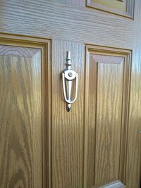
Obviously the door bell needs to be heard throughout the house, but it’s also important for the bell to be heard at the front door too. The caller needs that amount of feedback. In the case of a bell that rings in response to a knock, it gives the caller something to think about while waiting to see whether the door will be opened.
The first sensor I chose for this project was an inexpensive doppler shift module. It was ideal for sensing right through the door, and I aimed to detect the approach of the hand towards the door knocker, so the bell would ring without the need to even touch the knocker.
The module was much too sensitive. It had a range of 2-3 metres, or more. I could reduce the sensitivity by component changes, but that increased the standby current and the area of operation had poorly defined edges.
I moved on to a capacitative sensor, using the metal of the door knocker and a resonant circuit, whose resonant frequency would change when someone touches the knocker. Being unable to move the front door onto my work bench, I had to guess component values, then try it out at the door, go back, change components and repeat. This soon became too tiresome to bring to a conclusion.
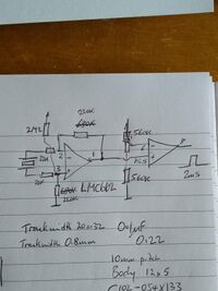
The next sensing device would be a piezo-electric disk. I prototyped an amplifier and a threshold detector and knocked on the bench with a pair of pliers. This worked!
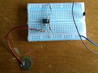
Initially I fixed the piezo to the front door with double-sided sticky tape. The detector responded to every action of the front door: the knocker, the letterbox, opening and closing the door, everything. Reducing the amplifier gain helped a bit, but there was still no distinction between the knocker and the other sources of vibration.
The door knocker incorporates an optical tube for seeing who’s outside. A spy-hole. That’s mechanically part of the knocker, and it conducts the sound of knocking through the door to the inside. The piezo disk needed to be wedged so part of the disk was resting on the spy-hole and another part of the disk was on the door. Then when the knocker is used, the piezo will be flexed by the vibration. Perfect.
I found I could reduce the amplifier gain from x10 to just x3 and still get a good result. Only the peaks of the output from the amplifier would be greater than the detection threshold, so that rattling from the letterbox or the door opening was ignored. Closing the door makes the door knocker move, yet this doesn’t set off the detector.
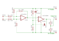
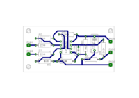
A second stage after the amplifier sets the detection threshold, and a little positive feedback through a capacitor lengthens the duration of the output pulse to 2-3 milliseconds. This is necessary as the output is sampled every 1ms. Without the pulse stretching there’s a chance the sampling could miss the knock.
File:KnockerCutCircuitBoard.mp4
I made a circuit board for the amplifier/pulse detector circuit, using Eagle for schematic and track layout, and I used the add-on ‘pcb-gcode’ to convert the PCB track layout into code to drive a CNC engraving machine which cuts copper laminate board to provide an isolating gap around all the tracks.
This process allows me to cut and drill a circuit board in about half an hour, compared with waiting 3-4 weeks to get it made cheaply in China, or 3 days in the UK at a prohibitive cost.
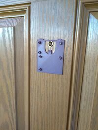
A 3D printed base-plate holds the piezo-electric cell, the circuit board and an additional circuit board which has a PIC processor and radio transmitter module. The base plate is held to the inside of the front door with double-sided adhesive tape.
When the piezo sensor detects a knock at the door, the PIC processor is woken from a low-power sleep and it uses the radio transmitter to signal to sounders within the house. The PIC also sends a signal to the bell module.
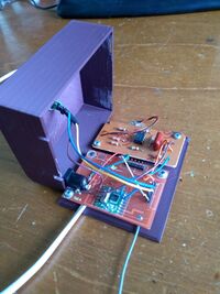
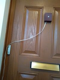
There’s a 3D printed cover for the base plate, and it is fitted with a PIR sensor, to inhibit the door knocker completely when it detects someone inside the house about to open the door. This reduces the chance of false triggering when the door is opened and closed. The wiring to the bell module needs to be tidied up, by running it in miniature trunking, but that's a task for another day.
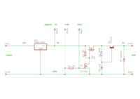
The bell module is a separate assembly, consisting of a battery, two voltage regulators and a bell. There is no convenient source of mains power near the front door, so the whole system is powered by a 12V rechargeable battery. A switching voltage regulator provides a step-down to 5V to operate the knocker sensor. It’s about 80% efficient, so that little power is lost in changing the working voltage.
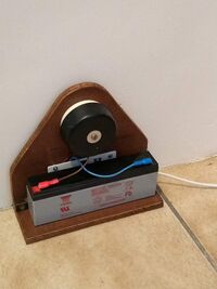
The bell requires 3V to ring, and this is derived from the 5v through a P-channel MOSFET acting as a switch and a PNP power transistor acting as a voltage regulator. While the bell is off, this arrangement takes no current at all.
The radio transmitter is normally off, the PIC processor is normally sleeping and the piezo amplifier takes very little current. The 1.2Ah battery is expected to last 6 months between recharges.
It’s been great fun to build and so far it seems to be working reliably, as intended.