Licence-free radio
Certain radio bands have been allocated for low-power short-range radio, and these bands can be used with no licence requirement.
In the UK, 433.90MHz, 868MHz and 2.4GHz are commonly used. The following article describes three PCB assemblies created by Ian B making use of a readily available radio-frequency module operating at 433.9MHz. The hardware and software are all open and can be adopted as they are or can be modified by anyone to suit any purpose.
Ian B's useful Radio Assemblies
There are currently three different PCBs each based on a Hope RF-12 radio transceiver module, a 14-pin PIC microcontroller and a power source. All three share similar hardware and software.
Some Applications
Detailed Description
The hardware provides connection for push-button inputs and 3v logic-level outputs to each pcb assembly. The software allows for individual unit IDs in the range 1-255, optional acknowledgement of data transmissions and a number of retries in the absence of acknowledgement. Radio data is intended primarily for point-to-point communication. There is no networking involved. This kind of radio is not intended for continuous or large-scale data exchange.
A single data transmission can cause the switching on or off of one or both outputs at the addressed pcb, or ON for a given number of seconds or minutes, or produce a given number of fast or slow pulses at the addressed output.
Software is written in C using a Windows-based C compiler (CC5X.exe) and is programmed into the PIC using a microchip programming tool. Both will run equally well using MS-Windows or using Linux with Wine.
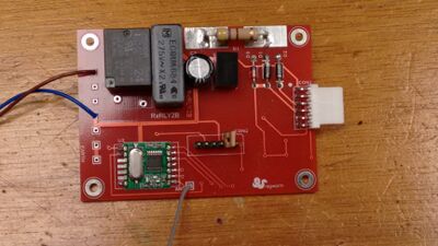
Mains-powered PCB Rx2

Although all three PCB versions transmit and receive equally well, one of the three PCB formats is best suited as an always-on receiver. It is mains-powered, though not electrically isolated from the main supply. It uses a capacitative voltage dropper, to supply 24v and 3.3v.
There is an on-board single-pole change-over relay connected to one of the two outputs. It can be used as a radio-controlled switched mains output. The second output is also capable of switching a relay, but the mains voltage dropper has not enough power to operate two 24v relays at one time.
There are solder pads for the mains in and out connections. Control outputs and inputs connect through a 6-way 0.1" single-in-line header. Repeat: the control connections are not isolated from the mains supply.
The PCB measures 83mm x 60mm.
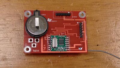
Battery-powered PCB Tx2

One of the PCBs includes a battery clip to accept a 3v 2032 Lithium cell. Outputs and inputs connect through a 6-way 0.1" single-in-line header. The PIC processor and the RF-12 radio module remain normally in a low-power mode.
Operation of any push-button causes a hardware interrupt, waking the PIC processor. The PIC starts up the radio module and transmits the message corresponding to the button pressed. It then waits for up to 10 seconds and returns to the low-power mode if there is no further activity.
With no button pressed, the battery will last for several years. If the processor sleeps with a push-button closed, there is a small additional battery drain due to current through the push button.
The PCB Tx2 has a build option where the 3v cell-holder is not fitted, and a DC socket is fitted instead. A 3.3v regulator is also fitted in this configuration. The PCB can then be powered by a mains-to-DC power supply rated at 5v to 15v and anything above 50mA.
The PCB measures 63mm x 44mm.
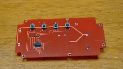
Battery powered PCB Tx3

The TX3 has four push buttons mounted direct on the PCB and provision for either two LEDs or one LED and a sounder, also mounted on the PCB.
The PCB has been designed to fit into a Type 55 hand-held case, with no connection for external inputs or outputs.
The Tx3 is powered from a 3v 2032 Lithium battery, accessible through a removable cover in the back of the case.
The PCB measures 120mm x 60mm.