Rewiring the CNC
Jump to navigation
Jump to search
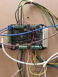
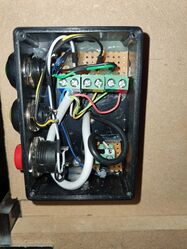
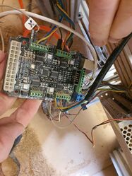
Photos as Ian and Andy's move the control board and power supply out from the path of the CNC
Manuals
Andy's_Adventures_in_CNC#Manual
Wiring Diagram
Current problems
Spindle
We think from the inverter manual that
- PD001= Decides whether control is manual or via the board
- PD002= Changes the incoming voltage based on the speed of the board
- PD070= Analoge Volage input - should be 1 (0-5V) as we've confirmed this is what the board is outputting
Results:
PD001=0 PD002=0 Spindle turns on/ off from controller but speed control dial doesn't work
PD001=0 PD002=1
- Without pressing green button M commands do nothing
- Error when pressing green button and issuing M commend
- Interestingly M3 (full on) doesn't work
PD001=1 PD002=1 Spindle should (?) be controlled by board but no M commands work
Photos
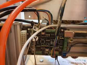
Current setup as of Jan 2021
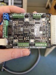
Board
Back
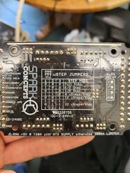
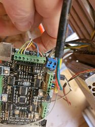
Jumpers
CNC estop box internals
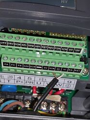
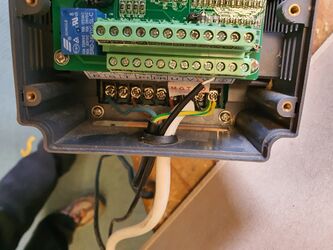
Spindle Inverter Speed control
This wire comes from the estop box to the spindle inverter front panel and delivered a 0-5V range
