Ian M's OpenSCAD stuff
Back to Ian M's profile
I'm collecting my OpenSCAD notes here. If you are looking for a tutorial for beginners you are in the wrong place as I doubt they'll ever be that well organized, but do check out my 'links' section below.
OpenSCAD is 3D CAD for people who prefer writing code to clicking and dragging stuff in a GUI, and repetitively entering numbers in text boxes! It uses its own declarative (functional) language to construct the object to render. In spite of its somewhat 'C'-like syntax, its very different 'under the hood' as variables are more like constants in other languages as they are immutable for the duration of their scope. i.e. a=a+1; is illegal. {ref}
Constraints are solely the responsibility of you the programmer to code and enforce. 'Vanilla' OpenSCAD without any libraries can be a PITA when constructing complex objects as you the programmer have to keep track of every dimension of every primitive shape to position them correctly relative to each other. However there are libraries that can hide much of the complexity - see below.
Customizer
The OpenSCAD customizer is very powerful, but by default, every variable that you define at the top level in your file before any module definitions appears in it. Often, that's not what you want as many of them are probably being used as named constants to avoid sprinkling magic numbers throughout your code. As the customizer only works on simple values, making the right hand side of the assignment an expression by appending +0, e.g.
C=299792458 +0; // Speed of light (m/s)
will exclude it from the customizer. Unfortunately enclosing the value in parentheses () is not sufficient.
Alternatively, as noted in the documentation section 'supported variables', exclude all subsequent lines of the file from customization, by defining *any* module with a compound body (i.e. wrapped in braces {} ), even if null. e.g.
module __Customizer_Limit__ () {} // end customizations
If you *do* want to let a variable be customizable, it is generally worth explicitly specifying its limits and increment (which must be numeric - you cant use expressions or other variables) on the line defining it so the customizer displays a usable slider for it, e.g.
lottoNum=13; //[1:1:49]
and if its name isn't self explanatory, provide a comment describing it on the immediately preceding line. Grouping related variables into 'tabs' (which extend till the next named tab) using:
/* [Tab Name] */
can greatly help clarify which variables do what.
Variable scope and special variables
Special variables are any variable with a name prefixed by $. Variables are immutable for the duration of their scope (either the file, or from the preceding { to the next } at the same level) and variables from enclosing scopes are inherited unless redefined. When you invoke a module or call a function, it does *NOT* inherit ordinary variables from its invoking/calling scope, but does from its definition's enclosing scope. Special variables are inherited from the invoking/calling scope so can be used to pass in data like parameters do. The *only* way to pass data back out of a scope is if that scope is the body of a function (from = to the terminating ;) as its return value. You cant 'leak' data from an inner to an outer scope via any type of variable. Running the sample code found at https://en.wikibooks.org/wiki/OpenSCAD_User_Manual/Other_Language_Features#Special_variables and carefully examining what it echoes to the console may help your understanding of OpenSCAD's scope rules.
So what's this $fa, $fs and $fn stuff? - smoothing arcs and circles
Some OpenSCAD special variables are 'special'er than others because they control how OpenSCAD behaves. $fa, $fs and $fn control how any constant radius curve or curved surface is rendered. That includes any sort of arc, and specifically the sphere and cylinder object primitives.
OpenSCAD doesn't and cant output real arcs or curves when it renders an object as it outputs the surface of the compound object as a closed mesh of triangles, so it has to break up any arc into straight line segments. $fa, $fs and $fn control the resolution with which it does so. $fa is the minimum angle each segment will subtend, $fs is the minimum segment length, and $fn overrides the other two if non-zero and is the number of segments to use for a full circle, reduced pro-rata for arcs of less than 360°. See the link above for how they are used to calculate the segment length. The default value of $fa gives thirty segments in a full circle, but the default value of $fs is one, so at a bit under 10 units diameter, circular objects will start dropping segments, eventually becoming pentagonal when they get small enough.
This is obviously undesirable when you are trying to construct a 3D printable part that needs bolt holes etc. You could override it by setting $fn but a high number of segments is computationally very costly - at least O(n²) for doubly curved surfaces - so setting $fn too high globally can lead to impracticably high render and preview times for complex models. Setting $fn locally is the best choice when a certain curved component or feature must be smoother than the rest. Otherwise, globally set $fs to an appropriate value for the print technology, 0.1 to 0.2 is 'in the ballpark' for most FDM print modelling, and set $fa to 360/N to choose the max segments N for larger circles. $fa still impacts rendering time, with smaller being worse, but at least you wont be attempting to render M3 bolt holes with μm precision!
Another common use for setting $fn locally - usually within the parameters of circle() or cylinder() - is to generate regular polygons and regular prisms. e.g.
cylinder(h=3.2, d=7/cos(30), $fn=6);
will generate a hexagonal prism the size of a M4 nut - 3.2mm thick, 7mm across flats. Note the division by the cosine of half the subtended angle of each face, to compute the diameter of the encompassing circle from the desired width across opposite faces.
To get a feel for their effect try the following which renders a stack of disks of decreasing size, and adjust the customizer sliders, remembering that $fn must be zero for the others to be effective. If it isn't obvious, zoom in on the smaller disks at the top of the stack.
$fa=5;//[1:60]
$fs=0.5;//[0.05:0.05:5]
$fn=0;//[0:90]

rs=[0.2,0.3,0.5,0.8,1,1.5,2,3,5,8,10,15,20];

for(i=[1:len(rs)]){
    r=rs[i];
    translate([0,0,5*(len(rs)+1-i)])
        cylinder(h=3,r=r);
}
Scripting OpenSCAD
You can run OpenSCAD from the command line and either silently render to a file or launch the GUI with command line options for preset customization or setting variables. See: Using OpenSCAD in a command line environment in its user manual for details.
Note that any variables set using the -D option have file scope and silently override any pre-existing file scope definitions for them in the file. They are persistent while the OpenSCAD GUI remains open. To clear the -D set variables, restart OpenSCAD!
-D <varname>=<value>
repeated for as many <varname> as you want to set, each with its own -D. If setting string variables you'll probably need to escape the quotes(") after the = and at the end of the string. See your OS specific documentation for command line / shell escape sequences for special characters.
As an example, see: Visualizing the bed levelling mesh in my CTC DiY I3 printer blog page, for how I send the bed levelling mesh data from a Pronterface script (Python) to OpenSCAD for visualization.
Text output
One of the output formats selectable is .echo - a dump of OpenSCAD's raw console log including echo() command output. It unfortunately suppresses other output, so to get e.g. a STL and a log file, you have to invoke it twice, to render twice. I have written a small command line utility in C, to extract specific echoed text from the log, discarding the rest, to allow OpenSCAD scripts to generate text files to pass to other tools. File:OCOparser.zip
#include <stdio.h>
#include <stdlib.h>

int main(int argc, char *argv[]){

   FILE *input_file;
   FILE *output_file;

   if(argc != 3) {
       printf("Usage: %s <in_file> <out_file> \n", argv[0]);
       printf("Parses an input file, generating an output file, consisting of those parts of the \n");
       printf("input file that are between an XON character and the next XOFF character. \n\n");
       return 1;
   }

   input_file = fopen(argv[1], "r");
   output_file = fopen(argv[2], "w");

   if(input_file == NULL || output_file == NULL) {
       printf("Error opening files");
       return 1;
   }

   int in_block = 0;
   char c;

   while((c = fgetc(input_file)) != EOF) {
       if(c == 0x11) { // XON character
           in_block = 1;
           continue;
       }

       if(c == 0x13) { // XOFF character
           in_block = 0;
           continue;
       }

       if(in_block) {
           fputc(c, output_file);
       }
   }

   fclose(input_file);
   fclose(output_file);

   return 0;
}
What's BOSL2 and why should I use it?
BOSL2 is the Belfry OpenScad Library, v2 (see link and description in 'Recommended Libraries' below). In this section I intend to show various cases where BOSL2 will make your life much easier. Lets start with:
Threading
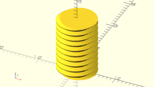
Threaded objects in 'vanilla' OpenSCAD, without BOSL2 or any other threading library are a PITA!
//M10 thread parameters
OD=10;
P=1.5;
L=15;
TD=0.92;

$fa=1; $fs=0.3;
<snipped 33 lines of support modules & functions + comments. See: File:NonBOSL screw.zip>
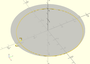
//Generate the thread cross section (XY plane)
shape2=concat(arc2l(OD/2,ang=[0,22.5]),arc2l(OD/2,ang=[22.5,135],ri=-3.2*TD),arc2l(OD/2-TD,ang=[135,225]),arc2l(OD/2-TD,ang=[225,337.5],ri=3.2*TD),arc2l(OD/2,ang=[337.5,360]));

linear_extrude(height = L, twist = -360*L/P)
polygon(shape2);  //Do the threaded rod
Note the complexity of building the cross section of the M10 thread, and that's before you even dig into what my arc2l() function does. It will probably take you an hour or two to match the thread form to the specification if you need to change it, and you have to look up the thread parameters manually for each size you want to be able to render
With BOSL2 that reduces to:
include <BOSL2/std.scad>
include <BOSL2/screws.scad>
$fa=1; $fs=0.3;
  screw("M10", length=15);
and you can simply specify the screw by named size. Apart from coarse and fine ISO (metric) threads, screws.scad also handles UNC and UNF and a couple of other. If you need a Whitworth or BA thread you'll have to provide the profile and use the generic threading modules in [threading.scad]
Pyramids!
Elsewhere 'M' wrote:
I use %GUI_CAD%, but struggle with it. Mostly because I use it infrequently and have to start over every time.
Last time, I wanted a simple 3D trapezoid (flat top pyramid) and could not figure out all the dimensions. I have not gone beyond dropping in simple shapes and modifying them. It would be easy some times to start with a cube and then draw a slicing plane or line to complete a plane, but none of that is apparent how to do.
(Nym and CAD software used anonymized for privacy) and I replied:
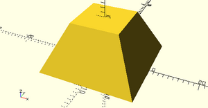
In 'vanilla' OpenSCAD, a truncated square right pyramid is simply:
rotate([0,0,45]) cylinder(h=10, d1=20*sqrt(2), d2=10*sqrt(2), $fn=4);
You may well ask what does a cylinder have to do with a pyramid? Well OpenSCAD allows you to use the cylinder object to make right regular prisms, by setting the number of vertices (and thus sides) with which it renders round objects. The $fn=4 thus gives four sides. You can also use the cylinder object for cones and frustums - you get a cone if you set r1 or d1 to the base size and r2 or d2 to 0 for a point at the top. Set r2 or d2 to a size smaller than the base and you get a frustum. The only remaining complexity is the *sqrt(2), and that's because when using $fn to make prisms, the diameter (or radius) gives the circumcircle, so we are effectively specifying the diagonal of the base and top squares, not their side length, so by Pythagoras, we need that correction factor. Finally as the circumcircle is divided into four equal sides starting with a vertex at angle 0, rotating it 45 deg about the Z axis brings the base and top sides parallel to the XY axes.
If you are using OpenSCAD with the BOSL2 library, its a lot simpler:
include <BOSL2/std.scad>
prismoid(size1=20, size2=10, h=10);
as prismoid specifically creates rectangular prisms and frustums.
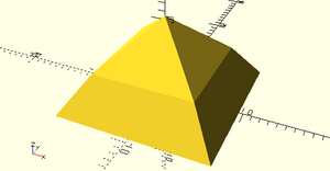
It also easily allows you to stack them e.g. to model the Bent Pyramid of Sneferu at a scale of 1:10000 (assuming the usual 3D printing convention of using mm as the unit):
include <BOSL2/std.scad>
prismoid(size1=18.943, size2=12.358, h=4.704) attach(TOP) prismoid(size1=12.358, size2=0, h=5.767);
I find it a lot easier to explore OpenSCAD, simply keeping the 'vanilla' and BOSL2 cheatsheats bookmarked in my browser, than it is to explore the myriad modes of %GUI_CAD% to find a reasonable method to do anything semi-fancy.
Bezier Curves
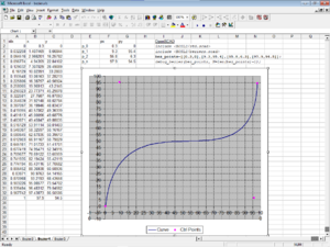
BOSL2 has various functions and modules to aid generating and using Bezier curves. However it lacks easy click & drag customization of the curve as the OpenSCAD customizer doesn't have any 'click in the plot' coordinate setting functionality, or even X and Y sliders for points, and also borks lists of lists, so I wrote an Excel 97 spreadsheet to generate OpenSCAD Bezier points lists for three, four and five control point Bezier curves.
It should work in Excel 97 - 2003. Excel 2007 onwards lack the capability to drag plot points*.
* It may be possible to get point dragging (or at least GUI manipulation) back with the (depreciated) MPOC addin (which you have to get from a 3rd party site as Microsoft have killed it and all related pages - try the Internet Archive [here] to download) but as I don't have Excel 2007 or higher, that's untested and YMMV!
A nose cap for the RML Dremel
The original went walkabout many moons ago and genuine ones are ridiculously expensive so we needed to 3D print one.
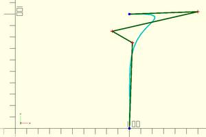
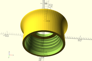
Note the use of multiplication by a scaling matrix:
bezier_points*[[Xscale/100,0],[0,Yscale/100]]
to scale the fixed size curve to the parametric cap diameter and length.
The complete code:
include <BOSL2/std.scad>
include <BOSL2/beziers.scad>
include <BOSL2/threading.scad>

//Dremel:
//thread len 8.8mm plain 2.5mm total 11.3mm#
//collet nut od 10.6mm

/* [Thread (US inch)] */
D=0.75;
TPI=12;

/*[Other Parameters (Metric)][*/
// Diameter of Dremel body at nose
OD=22.6;
// Length of noze
tl=11.3;
// unthreaded length at base of nose
ul=2;
// Thickness (additional length) of cap
cl=2;
// Hole dia. for spindle
id=12;
/*[Printer calibration]*/
//See BOSL2 wiki: Constants.scad: $slop: Calibration
$slop=0.3;//[0:0.05:0.35]
/*[Arc resolution]*/
$fa=5;
$fs=0.1;

module __Customizer_Limit__ () {} // end customizer
$dd=0+1E-3;
bez=[[100,0],[102.62,74.95],[85,85],[159.96,102.1],[100,100]];

*debug_bezier(bez, N=len(bez)-1); // show only with ! or exclude with *

pl=close_path(concat([[0,0]],bezier_curve(bez, 32),[[0,100]]));

//render() // only needed for graphics cards with broken OpenGL
diff("x"){
    // "x" cuts
    tag("x") threaded_rod(d=D*INCH, l=tl+2*$dd, pitch=INCH/TPI, internal=true){
            attach(BOTTOM,BOTTOM,norot=true)
                cyl(d=D*INCH+4*$slop,h=ul+INCH/(2*TPI),chamfer2=INCH/(2*TPI)) ;
            attach(TOP,BOTTOM,overlap=$dd)
                cyl(d=id+4*$slop,h=cl+$dd)
                attach(TOP,BOTTOM) cyl(r=OD,h=10)
            ;
            attach(BOTTOM,TOP) cyl(r=OD,h=10);
    }  //end "x" cuts
    down(tl/2) rotate_sweep(pl*[[OD/200,0],[0,(tl+cl)/100]]);  // Plain
    //down(tl/2) textured_revolution(pl*[[OD/200,0],[0,(tl+cl)/100]], "ribs",[2,0.2],tscale=0.6); // Ridged for grip
}
I printed it on my CTC DiY I3 at home, and it fitted my non-Dremel rotary tool nicely, so I knew the thread's OK. The next Tuesday I fitted it to the RML Dremel, and it turned out to be a very nice snug fit, with a barely noticeable ridge at the transition between cap and body.
TLDR: Use BOSL2!
There are few occasions when BOSL2 doesn't help you as an OpenSCAD programmer.
<under construction>
BOSL2 Issues
The documentation doesn't match!
Sometimes you find that when you paste (complete) example code from the BOSL2 wiki into OpenSCAD, it doesn't work and you get a WARNING: Ignoring unknown function ... or WARNING: Ignoring unknown module ... error, or various parameter errors.
Looking in your local copy of the corresponding BOSL2 library source file, you find the function or module has a different name or is simply missing, or its parameters are different. This usually doesn't mean the wiki is wrong, as its a big hint that your BOSL2 is out of date and you need to download it again (as the documentation is usually updated to reflect the current state of development). Archive a copy of the previous version in case the new version breaks any of your older OpenSCAD BOSL2 projects.
There is a BOSL2 version number, currently* 2.0.716, which you can interrogate but it isn't as useful as it should be for checking code compatibility as it hasn't been incremented in four months, and usually isn't 'bumped' for changes that break backwards compatibility! e.g. back in 2022/2023 it went close to a year without a version 'bump'
* as of June 2024
Reading the BOSL2 documentation on Github restricted
When browsing the BOSL2 wiki, while not logged in to Github, you may get an error page:
- Access to this site has been restricted
It can be triggered by only following a few links, and is persistent, blocking all access to any Github pages (including login). It is believed to be related to the number of large images on some of the BOSL2 wiki pages resulting in hitting a bandwidth threshold when skipping through pages. It may clear after ten minutes inactivity. Alternatively try clearing all Github cookies and restart your browser. If you get it, you will need to log in to Github to prevent it recurring, as persisting unauthenticated may result in an IP ban.
Rendering can be slow and CSG export bloated
BOSL2 does a lot 'under the hood', all in native OpenSCAD, and makes it easy to create very complex objects. The downside is number of [CGAL https://en.wikipedia.org/wiki/CGAL] operations it must perform to render the stack of attached non-simple objects you have built your model from, and lines of code it must generate for CSG export. If you end up with long render times for seemingly simple models, or they are too complex to import into FreeCAD, it often means you have made bad design choices, and maybe you should consider swapping additive modelling for subtractive modelling for all or part of your model to simplify it, or consider extruding all or part of it from a 2D cross section, which is also beneficial as a workaround for graphics cards with broken OpenGL!
Laser Cutting with OpenSCAD
Has its own page: OpenSCAD to Laser Cutter
Also see: B. M. Sleight's Lasercut library (link below)
Measuring stuff in OpenSCAD
OpenSCAD unfortunately doesn't let you select stuff in the render window, or drag stuff and get a numeric position, but sometimes it is useful to be able to get dimensions off a rendered object. It is a fundamental limitation that you cant interrogate rendered geometry. My answer to that is a cursors library that generate two XYZ crosshairs that you can move around by customizer sliders or 'bumping' the coordinate directly, so you can visually line them up with the features of interest, zooming in to whatever level of accuracy you require, and read off the distance between, azimuth and elevation in the console window. Get it here: File:Cursors.zip
Recommended Libraries
https://github.com/BelfrySCAD/BOSL2 - The Belfry OpenScad Library, v2. A massive 'Swiss Army Knife' library that handles nearly everything you'll need to construct complex objects. e.g. attaching child objects to anchor points on a parent without having to worry about their absolute position, rounding/chamfering edges and corners, screw threading and more other stuff than you can shake a stick at. My #1 recommendation for *any* OpenSCAD user.
https://github.com/bmsleight/lasercut - B. M. Sleight's Lasercut library handles extracting 2D geometry from components of a 3D model and 'plating' the result for laser cutting. See full description in the Libraries section of my OpenSCAD to Laser Cutter page
Useful Links
https://mastering-openscad.eu/ - "Mastering OpenSCAD: within 10 projects" by Jochen Kerdels, ISBN: 978 3753 458 588
The book Mastering OpenSCAD introduces you to all important concepts and functionalities of OpenSCAD. The book guides you through 10 selected projects step by step, each project focusing on a limited set of functions and concepts. After these 10 projects, you will know all practically relevant features of OpenSCAD. For the sake of completeness, a final chapter briefly presents the functions that were not addressed in any of the projects.
Read online for free [here], single document (accessible) version [here] or buy the paperback from Amazon.
https://www.reddit.com/r/openscad/ - Reddit: r/OpenSCAD - a fairly popular* unofficial forum for OpenSCAD discussions. The official forum originally was integrated with the OpenSCAD mailing list, but Nabble broke that so its mostly inactive.
* 29 threads in the last month, when I wrote this.